I’ve changed my mind on microcode sequencing. Again. Ok, I know I would be fired if all this was for real, but I don’t like the sequencer design with ‘next’ field embedded in the microcode word anymore. The problem is with the ‘next’ field itself which I planned to be longer that 8 bits. This requires not only more EEPROMS but also more chips for multiplexing and latching of different inputs (opcode, next field, priority encoders) and as such will be difficult to build and test. Besides, I have limited space on my wire wrap boards. Of course, I could limit the ‘next’ field length to 8 bits and use some additional logic to choose the “page” in the microcode store (depending on whether we are decoding an opcode, branching or processing fault or interrupt) as Bill Buzbee did in his Magic-1 design. This decreases the ‘next’ width and the number of multiplexing chips but increases the overall complexity and requires more effort and lots of microcode optimizing to fit it into limited storage (Bill managed to compact his microcode to 512 words). As this is my first electronics project ever, I feel now I should keep things as simple as possible. Thus, the microcode sequencer will be driven by a 5-bit microcode step counter. Period.
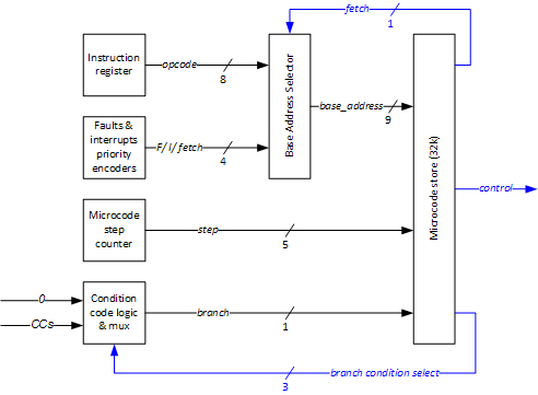
So, here is the final picture:

Here, the 32k microcode store is fed with 15-bit address which is a concatenation of:
- 9 bits of base address
- 5 bits of step counter
- 1 bit for selected condition code
Base Address
Base address is selected and latched in the Address Selector, based on its inputs which are the instruction register (8 bit opcode) and priority encoders (4 bits). The Address Selector realizes the following logic:
- if the PE outputs a fault code, the Address Selector feeds the EEPROMS with the base address of a corresponding fault’s microcode (at the same time the step counter is also asynchronously reset)
- if the PE outputs an interrupt code AND the microcode indicates we are done with the current instruction ready to fetch the next instruction (a dedicated 1-bit signal), the Address Selector is latched on the next tick of the system clock and feeds the EEPROMS with the base address of a corresponding interrupt’s microcode (again, counter is reset, but synchronously this time)
- if the PE outputs a fetch code (lowest priority selection) AND the microcode indicates we are ready to fetch (like in the scenario above), the Address Selector is latched on the next tick of the system clock and feeds the EEPROMS with the base address of a fetch microinstruction (counter is reset)
- otherwise (not a fault OR fetch line is not active) the instruction register contents are latched and the Address Selector points at the address of a visible CPU instruction
Visible instructions will be located between 000h and 0FFh. Faults, interrupts and fetch will be between 100h and 1FFh. The Address Selector will map the inputs onto correct 9-bit addresses in the microcode space space (some zero-extending for 8-bit opcodes and some OR-ing for 4-bit PE output will be necessary here).
Step Counter
Step counter generates a sequence of 5-bit binary numbers. This code is used to point to a correct microinstruction of a currently processed CPU instruction (or fault/interrupt microcode). Since it is 5 bits, my instructions will take up to 32 cycles (more than enough).
Step counter is increased on every system clock tick and it is reset whenever Address Selector is latched (see rules above).
Condition Code Mux
Condition code mux outputs a condition code which is selected by the microcode’s 3-bit branch condition selection. This means that each microinstruction is further divided into 2 planes (condition met and condition not met). Which plane is selected depends on the value of a selected condition code. This way, we will conditionally branch in the microcode.