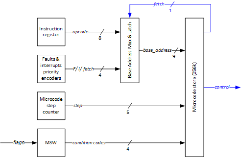
When I started writing first microcode and sketching the overall block diagram I decided to tweak the microcode sequencer again a little. Here’s what has changed.

Fetch. The 9-bit base address points to two 256-element pages. Addresses in page 00h-FFh store instructions directly visible to programmer, whereas page 100h-1FFh is reserved for pseudo-instructions which are not visible – faults, device interrupts and an isolated fetch microinstruction. In this approach fetch is always executed in a dedicated clock cycle. Since I will have disjoint ALU result bus and memory data bus, in some cases it is possible (in terms of bus availability) to fetch the next instruction while still performing operations within the ALU. So, I decided to give up an isolated fetch and incorporate its microcode into each instruction. This way I am occasionally wasting one counter step (when fetch is still isolated in the last microcode step) but with 5-bit counter (32 steps) this should not be a problem. The logic for Base Address Selector (now renamed Base Address Mux & Latch) is the following:
- if the PE outputs a fault code, the fault address is asynchronously fed as the base address and step counter is asynchronously reset
- if the PE outputs an interrupts code AND we are done with the current instruction (a dedicated 1-bit signal generated by fetch microcode), the interrupt address is latched and counter is reset on the next system clock edge
- if the PE outputs a lowest priority selection (no faults/interrupts) AND we are done with the current instruction (as above), the IR contents are latched and counter is reset on the next system clock edge
Condition codes. Previously I wanted to save some microcode bits and the microcode output included a 3-bit condition selection which was fed into a condition code mux which in effect set the selected condition code value as one of the inputs to the microcode store. This caused a loopback in the microcode which would cause unacceptable latency (the condition code and microcode output would ripple until stabilized and even with 70ns fast FLASH EPROMs a pessimistic 140ns should be assumed in any timing considerations here). So, I decided to give up multiplexing and feed the microcode store with all 4 flags (N, C, V, Z) directly from the MSW (yet to be designed machine status word). Of course, this means that we no longer have two conditional microcode planes (condition met and condition not met) but 16 of them (for all possible combinations of four flags). This is an awful waste (only few combinations are really used) and I wanted to avoid this when thinking about the sequencer driven by a ‘next’ address, but for the sake of simplicity and speed, I believe this is what needs to be done. With this approach I now a total of 18 bits of microcode addressing, which results in a required EPROM capacity of 256kB. I could use something like this for this purpose.
4-bit Counter?My first microcode indicated that I am using not as many microcode steps as I had anticipated. This means, that it may be possible to use a step counter of just 4 bits instead of 5 (and just one 4-bit counter chip instead of a combination of a 4-bit counter and a 1-bit flip flop). I have not done complex fault on interrupt microinstructions, though. For now, I am leaving it as is.