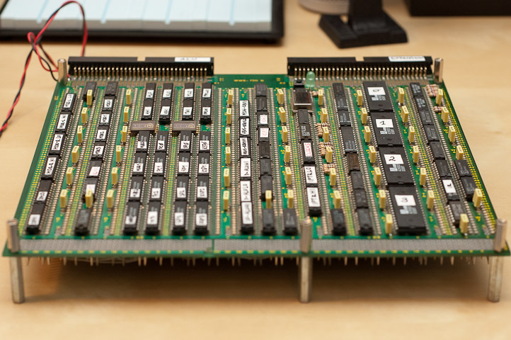
I have finally completed wire-wrapping the CPU’s main board. It consists of 82 ICs, 51 power filter caps, 26 resistors, one oscillator, one power led, one reset button, two HP hexadecimal displays, two 64-pin IDC headers, a molex power connector and lots of AWG 30 kynar wiring. In fact, there is around 1600 wires, and 3200 wraps. Many things could have gone wrong with so much manual work. I tested all connections using a continuity probe, but there is a risk I messed up some wires when wrapping consecutive ones. I hope there are no shorts, broken wires, loose wraps or alike. I connected the board to the power supply and it seemed to be all right – the HP displays indicated a stable $FF value on a LBUS (left ALU bus), power draw was stable at 450 miliwatts, and nothing was overheating. It’s quite promising. As previously announced, the ALU part of the CPU did not fit on the board and will be assembled on a separate one (hence, the ALU connector on the right). It is still wire-wrapping but the board is less complex (fewer components) and should not take long to build. But first I will solder the memory board and try to run some rudimentary programs without using the ALU (this seems to be doable since some of my registers, including the program counter, have increment signals, and there is no need to use the ALU to advance them). Yet before I go any further, here are the latest shots of the machine. First, the components side:

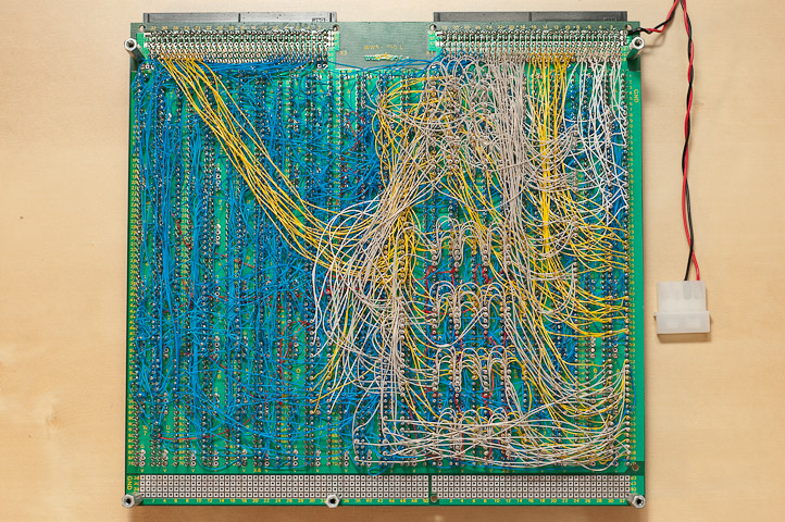
And here is the wire wrap side. Molex power connector is visible on the left hand side. Signals other than blue are clocks (red wires) and buses (yellow, white and gray wires). I tried to follow this color code to be able to rework the wiring if there is such need (although I am hoping not to). Altogether, it looks like a nice kynar carpet:

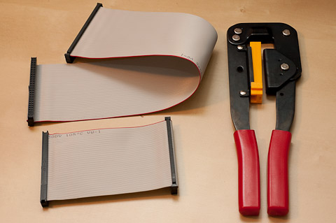
To connect my other boards I assembled backplane ribbon cables. I used a gray 64-wire ribbon cable and compatible connectors. I made two cables. The shorter one will be used to connect the ALU board and ALU board only. The longer one will be used as a peripheral connector (expansion bus) to connect the memory cards and any future expansion cards (UARTS, keyboard, IDE, video and alike). The backplane connector is 0.35 m long (~14 inch) which should be enough considering all my cards will fit in a 19-inch rack (taking into account than the future “production” CPU will be built of 5 stacked PCBs and use 5 inch). I could have made it longer (e.g. full 19-inch) but I am afraid this would compromise signal integrity. This ribbon works as an antenna, so the shorter it is the better. One thing worth pointing out here – you need a tool to crimp IDC connectors. The operation requires too much force to be able to do it by hand. I used a crimping tool visible in the photo. I got it from a local store for the equivalent of 10 euros (15 dollars). On YouTube, I have seen people use a regular garage vise for the job, but I don’t have one at home so I had to invest some money in the tool. Here are my backplane connectors nicely crimped:

As said, next I will solder the memory board I have had manufactured by BatchPCB. I will report on progress soon so stay tuned.