 Soldering is so much faster than wire wrapping, and my last evening’s session proves that. I managed to complete my base memory PCB in two hours, from workshop setup to actual soldering to plugging all parts into their sockets. This exercise was so encouraging that I am seriously considering building the ALU part of the CPU on a custom board, too. The problem is that the connector I planned between the wire-wrapped prototype of the core CPU and the ALU is not what I will ultimately use in “production” CPU built on PCBs (with boards stacked and connected using goldpins headers, not a 64-wire IDC). This means that this board would be a protoboard by definition, not to be reused later. However, the amount of time I save might be worth some extra dollars. I think I’ll need to say hello to BatchPCB again.
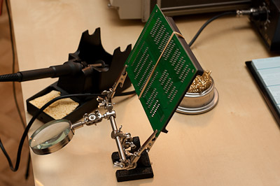
Back to the point. The photo to the right shows my yesterday’s workshop setup. I used third hand tool to hold the board in place, a piece of plastic and a rubber band to press the sockets to the board (I used precision sockets for all components). My iron was a PT 936 which I bought online a couple of weeks ago. Iron temperature setting was 400 degrees celcius (750 degrees F). I also had an iron tip cleaner handy, to keep the tip clean at all times. I use a soft wires cleaner. Some people say it is enough to use a damp sponge (most soldering irons come equipped in sponges) but I think the thermal shock of the tip in contact with a sponge is just not good for it. Golden wires work very well in that respect.
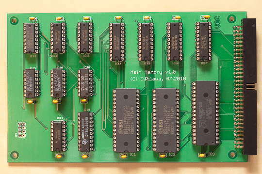
Even though I prepared for the task carefully, I was not happy with my first joints (I still hope they’re not cold joints). After a short while I found the correct iron grip, tip temperature and the amount of solder. The result of my work is in the photo below.

There are some lessons learned from this experience:

Use the correct iron tip for the job. I used a 1mm cone tip which I think now was too small. I was having trouble heating some pads (especially those adjacent to power or ground planes) and leads properly to make a good joint. I immediately ordered two larger iron tips last night (2mm cone and 1.6mm flat).
Use the correct solder size for the job. I started with a 0.5mm rosin core solder with a hope of being more precise. It soon turned out that 0.5mm was not enough to make good joints – solder was flowing into the mounting holes and it was taking too much time to build up a decent joint. I changed it to 1mm rosin core solder and it went smoother.
Use Eagle’s “thermals” setting when adding power or ground planes. Otherwise, soldering pads embedded into copper planes (such as VCC and GND pins of the ICs) will be extremely difficult (unless you have a better solder tip I used). The reason for this is that a copper plane acts as a heat sink, making it hard to heat properly. Thermals isolate such pads from a copper plane, connecting them only with traces of say, 12 mils, thus protecting you from unwanted heat transfer. Funny, when I first came across this option in Eagle I was thinking why the name was “thermals”. Now I know.
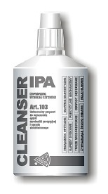
Clean your board from rosin (flux) residue after you are done. After soldering, your board is covered with flux residue (rosin has a tendency to splash like hot oil on a wet pan). I knew this would happen so I was prepared in advance. To clean a board, you need alcohol cleanser. I used the one visible in the photo, but any isopropyl will work just fine. To apply cleanser onto the board and clean it I used a toothbrush.