It’s been nearly a month since I last posted. Unfortunately, there hasn’t been much progress recently. I have only a few hours every week which I can fully spend on project activities. Big part of the reason is that I will be moving from Poland to Germany for a while, and there is a lot of arrangements I had to make (mostly related to transfer process within my company). Hopefully, things will get back to normal sometime soon.
Meanwhile, I have been testing my almost-finished CPU and the memory board. As a reminder – there is still no ALU, and ALU buses are electrically floating, resulting with binary all-zero or all-one bus values. Still, I was able to run basic tests without exercising the ALU functions. Surprisingly, even though I am pretty sure I tested all connections with the continuity probe while I was wrapping them, I am still finding bugs. Most of them are simple wrapping mistakes (e.g. wire is on pin 29.56 instead of neighboring 30.56) and not design flaws. I have also found one schematic flaw (swapped signals in microcode sequencer’s muxes). In total, I have tracked about a dozen bugs so far. The sequencer bug will be fixed in the next schematics release (1.0.2). The diagram currently available for download (version 1.0.1) still has this bug. I am sure I will find some more so I will probably wait until first real boot-up to publish the new, cleaned-up schematics.
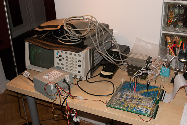
Testing setup occupies my entire desk. Here is a photo of work in progress (the memory board did not make it into the picture, though).

Not quite completed, my CPU can already run simple programs, provided they do not require the ALU. As an example, here is a little code snippet:
start:  ld a, 0x0705   ; 21 07 05
        push ah        ; c3
        jmp start      ; 1c ff f9
The code does nothing useful, except for cycling successfully through these three instructions. Their microcode is:
// LD A, #i16
op($21)
	0, *, HI(A) <- MEM(PC); CODE; PC++
	1, *, LO(A) <- MEM(PC); CODE; PC++
	2, *, fetch
endop

// PUSH AH
op($C3)
	0, *, SP--
	1, *, MEM(SP) <- HI(A)
	2, *, fetch
endop

// JMP #i16
op($1C)
	0, *, HI(MDR) <- MEM(PC); CODE; PC++
	1, *, LO(MDR) <- MEM(PC); CODE; PC++
	2, *, PC <- MDR + PC
	3, *, fetch
endop
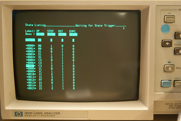
As you can see I am using only PC++ microinstructions to advance the program counter (without using the ALU). Yet, you may think this can’t work because the last instruction (opcode $1C) needs the ALU to function in step #2. True, but if you consider floating ALU buses, the microinstruction will load the address $FFFF to PC, and later fetch the instruction at that address. Since there is also $FF value at uninitialized memory address, it will fetch the unused opcode $FF. In my design unused opcodes are effectively the fetch microinstruction, so the control will jump back to memory address $0000 (program counter will roll over) and the program will start again. Here is a shot of this code running as seen on my analyzer’s display:

The contents of the IR (instruction register) are in the column labeled OP. There is also the step counter value on the display, /RESET and /ENPC (program counter enable) signals. This setup is not showing the data bus but I have tested that the first instruction loads $0705 from memory into A register. Everything looks as designed, which is encouraging. You may think this is not too impressive, but it took a lot of effort to get to this point. It proves that at least the microcode sequencer works correctly. I feel I am getting closer and closer to my first real computation.