I now have a computer with support for RS-232 serial communications. Since my last post I managed to build and preliminarily test the new device card with two 16550 UART chips. Somehow it makes me very excited, because for the first time I will be able to communicate with my system by means of keyboard and monitor. It is starting to look and feel like a real computer now. Also, this creates brand new opportunities. I may now seriously consider rudimentary operating system, and “useful” interactive programs.
First, let’s see how I progressed with the construction. I used a new technique for wire wrapping using prototyping perfboards and soldering together precision sockets and breakable pin headers (with square cross section). Square cross section is particularly important for wire wrapping, as otherwise I wouldn’t be able to wrap wires reliably and they would easily slip off the posts. Here is how it looked like (note the pin headers corresponding to precision sockets):
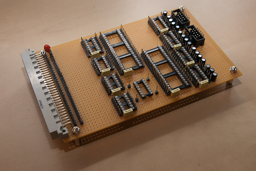 This thing was pretty difficult to solder. My perfboard has copper individual soldering pads for each hole. In order to bridge the precision socket and the header leads I had to make solder blobs big enough to make a reliable connection, and small enough to keep them off neighboring pads. If you ever decide to do it, make sure you have a decent solder sucker or a length of solder wick. Re-doing joints is part of the job here. Here is the end result:
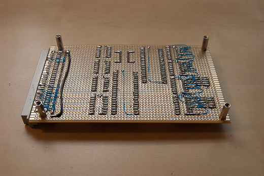 In some cases I needed to create more distant connections (for capacitors and for bus connector) so I used a wire-wrapping wire and soldered it underneath the board where necessary (blue wires in the photo). After soldering, I was able to populate the top of the board with fresh chips and connector ribbons:
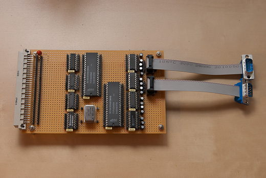 So far so good. The board at this point looked neat. Things got a little worse when I completed the wiring:
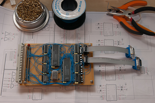 Overall, I am not too happy with this method. It looks messy and I fear that it is easy to accidentally break a wire by improper handling. I have already tried wire wrapping on dedicated wire wrapping boards (the entire CPU), making custom PCB at a board house (memory card) and now this. I think I will etch my next board at home using toner-transfer method. This should be a good trade-off between professional PCB (elegant but expensive) and wire-wrapping (messy but modifiable at zero cost).
Having completed construction, I immediately connected the entire setup to my laptop. Of course, it failed on the first attempt. I made a mistake on the schematics and replicated it in the wiring. I wired active high chip select inputs of the UARTS (CSO and CS1) to ground instead of VCC. This way, both chips were always deselected, regardless of the state of low active /CS2. Fortunately, the fix was quick and easy. On second attempt, I got this message on my laptop screen:
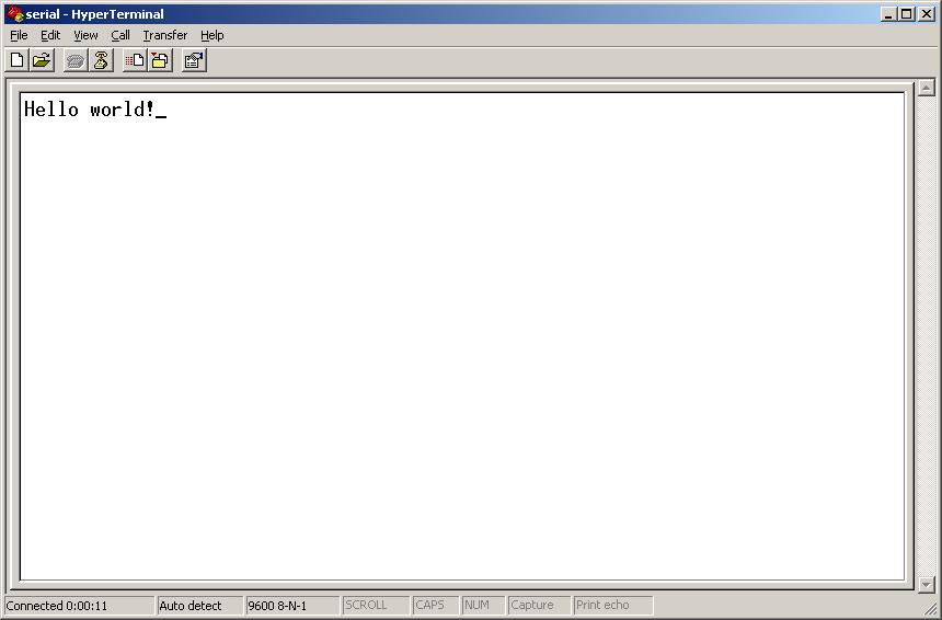 Believe it or not, but the message actually comes from software executed by the CPU. For now I am testing at 9600 baud with no hardware or software flow control, but my hardware should support both XON/XOFF and RTS/CTS. At least I have wired all necessary connections. With the new card, the entire setup draws roughly 1.62 amperes and still, although a little surprisingly, runs flawlessly at 4.09 MHz.
The updated schematics is as usual in downloads. I think my next step now will be to update (or re-write) the assembler. The current one was put together quickly using lex and yacc for testing purposes and is very limited. It has no support for constants, it is unable to dump literals (e.g. strings) nor can it switch between code and data segments. It also generates absolute assembly. With these limitations, even the “Hello world” code snippet looks like raw disassembly. I definitely need a more sophisticated assembler to write useful software.
Czekalam na te slowa 2 lata …
A Hellow World message is always exciting, isn’t? –very good! Just one word of advice on soldering: I don’t think solder blobs are good for bridging your IC socket pins with your wirewrap header connectors; you should employ short naked wires instead. As per the mess of wires, you could place some kind of guides to accommodate the wires into ordered hardnesses; this would make it look better and (more importantly) helps in preventing wires to get of by accidental handling.
I will adopt the same technique for my next board. The soldered-wires technique I’ve used so far has worked fine but it takes too long for wiring a single board… so I’m putting my hope in this low-cost wirewrapping method you used.
Question: Did you experienced the timming issues mentioned in your post “Serial ports (based on 16550D UARTs)” ?
Strange, but so far everything runs flawlessly at 4.09 MHz without “slow clock” circuitry. I think I need to break out my logic analyzer and see how close I am to the limit.
I guess what happend is this: It takes more than one clock cycle from selecting to actually reading the device. Your clock period is 250ns so two periods are 500 ns, more than enough for this “slow” device.