The EPROM emulator I mentioned in my last post now works with the memory board. Making it work was an easy task and required a few simple hacks in hardware and software. Now I have a convenient and reliable development environment based on real hardware, and free of the hassle of EEPROM programming. I know that having a full software emulator is inevitable and I do plan to write it in a few weeks from now, but a hardware emulated EPROM seems to be a nice concept temporarily and I will stick to it for a while (at least until I complete all hardware parts which I still plan to develop).
Time permitting, I will continue Monitor/OS development now and write software demos to show that the computer is capable of doing more complex things than just printing strings of characters to a terminal screen. To do that, a C compiler may be required so I need to start looking in more detail at LCC, too.
Hardware tweaks
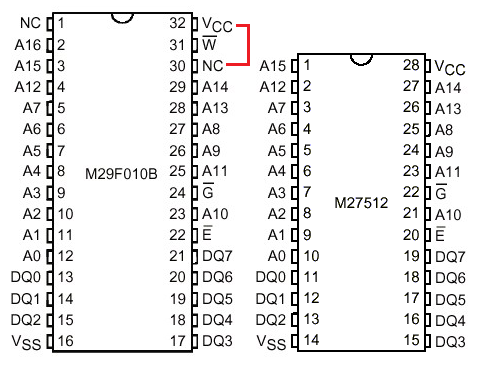
Coming back to the emulator – I thought the biggest challenge would be to adapt its 28-pin DIP probe originally designed for 27512 65k UV-erasable EPROM to the socket of a 29F010 128k EEPROM I am using as a ROM chip. Adapt or build a completely new one, depending on the ultimate complexity of the task. A quick look at the pinouts of both chips revealed that it would be a simpler task than I had expected. These chips have almost identical pinouts, only that the 29F010 has one more address line and comes in a DIP-32 package. I realized I could easily use the 28-pin adaptor, plug it into the DIP-32 precision socket of my ROM and have all relevant signals match, except for the VCC. However, I was lucky enough to find that the pin used for VCC in 27512 matches an unused (internally not connected) pin of 29F010. I modified my memory board slightly using a piece of kynar wire and connected the VCC (pin 32) and NC (pin 30) of the ROM socket (see drawing to the right). It makes absolutely no harm to 29F010 when it’s plugged in and powered, and with this setup and the 28-pin adapter plugged into pins 3 through 30 of the socket, I have a pinout compatible with the 27512. Of course, A16 remains always unconnected during emulation, which means that I may only use 64kB of ROM in the software I run, but 64kB is the limit of the emulator anyways. The attempt to address memory range $10000-$1FFFF (A16 set) during emulation will default to the emulated range $0000-$FFFF (as if A16 was unset) because A16 is basically ignored in such case.
Software and bring-up
Hardware tweak was not enough, though. I had to update the assembler, too. Some time ago I dropped support for flat binary output in a belief that I would be only burning EEPROMs. So my assembler could only output Intel HEX files matching my memory model and size – 64kB for code starting at $0000 and 64kB for data starting at $10000. This worked perfectly with EasyPRO 90B programmer and 29F010 chips, but not with a 64kB emulator. Moreover, since the EPROM emulator is basically a printer as seen by the PC to which you do a simple binary file copy I needed flat binary image files again as assembler output. So I added a format selection command line switch with additional option to define memory segments entry addresses. For example, these commands first generate binary output of the assembly with code segment starting at $0000, and data segment starting at $8000 (with empty space is filled with zeros) and then dumps the binary into the emulator by doing a file copy to a “printer”:
./as example.asm -o examble.bin -f bin -a 8000h
sudo cp example.bin /dev/lp0
I have made the new assembler revision available in downloads.
Last but not least, I had to update the OS/Monitor assembly so that the memory setup routine maps correct memory segments of lower 64kB of ROM on startup. This was in fact the easiest part. Having put all the parts together, I gave the emulator the first try, but it failed. I spend a few hours trying to investigate the problem, suspecting signal integrity or some sort of incompatibility between the emulated and host chip type. I did not find any problems. Then I realized that the emulator, with its additional buffers may be increasing the propagation delay enough for the entire setup to fail above a certain clock speed. I replaced the clock generator to a 2MHz one and it helped immediately. I run at reduced clock speed during software development, but that’s not a problem.
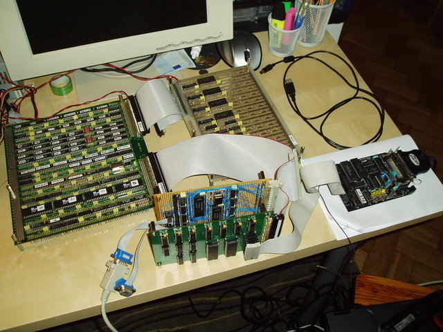
All in all, now I have this tangle of ribbons and boards constituting a CPU with its peripherals and an emulated ROM:

I’ve already ordered my own emulator PCB and necessary parts at AVT (it comes as a self assembly kit). It should arrive in a couple of days.