There are two things in my design still missing to declare completion of basic hardware – real-time clock and IDE interface. Hence, my recent project activities concentrated on these two elements. RTC and IDE will occupy a dedicated expansion board and will be built in a way to keep hardware complexity to the minimum.
RTC
For the RTC I was looking for an integrated chip with parallel interface (I really hated the idea of interfacing via I2C) and requiring minimum amount of external components. I have chosen bq4845 because it meets both criteria and was available for free from Texas Instruments’ samples program. I registered for the program, selected the parts I needed, check-out with $0.00 payment due and after a few days I had fresh, neatly packaged parts delivered by UPS (I ordered a bunch of MAX232s and some other stuff, too).
As to the bq4845 itself – the IC comes in a 28-pin wide DIP package, is fully TTL compatible and has the following features I needed:
- BCD real-time clock with 1s resolution
- 100-year calendar with automatic leap year adjustment
- Programmable periodic interrupt with 30us to 500ms period (which I will use as heartbeat timer for the CPU)
The bq4845 also has a programmable watchdog timer to monitor CPU operation, programmable alarm clock interrupts, battery low warning and battery backup switchover circuit to build nonvolatile RAMs but I am not planning to use any of these features. What I liked most about the bq4845 was that it requires only two external components – a 32768Hz clock crystal and a 3V battery for power backup (I plan to use a CR2032 cell). Add to that basic address decoding and it is really all you need to hook-up a real-time clock to your project.
The bq4845 provides 15 programmer accessible registers which I mapped to addresses in range 1020h-102Eh of supervisor data memory. As to IRQ assignment, I have tied the chip’s low active interrupt line so that it would pulse a /IRQ7 (lowest priority interrupt line) providing a CPU heartbeat for multitasking, synchronization, precision time sampling, etc.
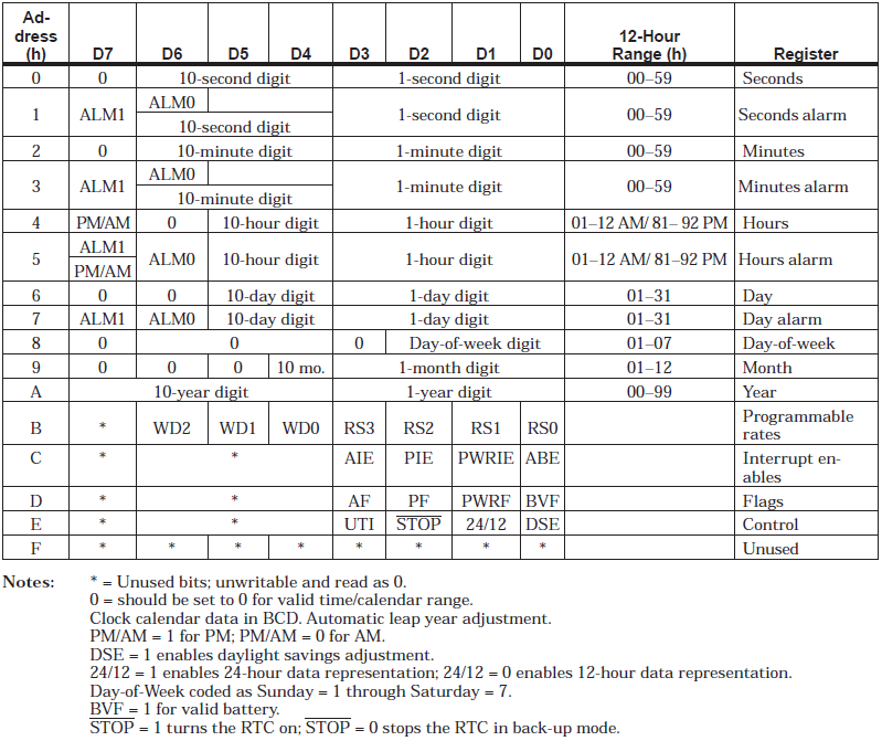
Here is the register table (from bq4845 datasheet):

The meaning of registers is self explanatory. Addresses 0h to Ah provide clock and calendar data in BCD. Register Bh is used to control programmable rates of both the watchdog timer and periodic interrupt (heartbeat). Register Ch provides interrupt enable flags (alarm, periodic, power fail). Registers Dh and Eh are status flags (interrupt status, battery status) and control registers (stop clock, 12/24h mode, daylight saving setting) respectively. Offset Fh is unused.
IDE interface
For a long time I thought of an IDE interface as of something very complex. In fact, the basic interface is fairly easy to implement with just a few components. Naturally, if you think of FIFOs, DMA and all that extra stuff real IDE controllers have, things are getting more complex. However, for my use to implement a basic PIO mode 0, you may think of an IDE as of just a different layout of CPU expansion bus, or a device exposing a set of I/O ports plus some control and status registers. I based my design on hints I have found on the Web (where else?) here and here.
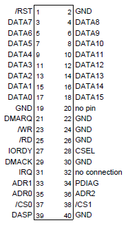
The 40-pin IDE connector provides the following signals:

Not all of them are relevant for a simple implementation like mine. I am using the two chip select lines, three address lines, reset and interrupt lines, read and write lines and DASP line (this one only for HDD activity LED). Other pins are unused and they are tied to either power or ground (see schematics below for details).
The only real difficulty in implementing an IDE interface is that is a 16-bit interface whereas my CPU uses an 8-bit bus to access memory. To solve this problem I implement 2-phase reads and writes. I use two 8-bit scratch registers for that purpose and accessing IDE data will always require a little preamble (write) or postscript (read) in the code. Those two 8-bit scratch registers are used to latch the upper 8-bits of a 16-bit IDE bus when reading or writing. Proper read and write sequences are as follows:
- Read phase 1: Read data from IDE register directly. Only lower 8-bits are read by the CPU. At the same time, the 8-bit scratch register latches the high byte of the 16-bit IDE bus.
- Read phase 2: Read the high byte from 8-bit scratch register just latched (mapped in memory under different address).
- Write phase 1: Write to 8-bit scratch register that will store high byte of the 16-bit IDE bus.
- Write phase 2: Write data to IDE register directly. Lower 8-bits of the IDE bus are fed directly by CPU data bus. At the same time the scratch register pre-written in the previous step drives the high byte.
This approach requires extra CPU code to handle 16-to-8-bit mapping but simplifies the circuitry a lot. All in all, a simplest IDE interface is doable with just a few TTL components.
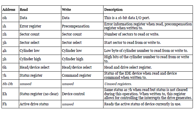
For the CPU the IDE interface appears as the following registers mapped to memory region 1030h-103Fh (note – only the data port is really 16-bit, other registers read or write meaningful data in lower 8-bits only so there is no need for 2-phase reads and writes):
 I have mapped the scratch registers for 8-to-16-bit mapping to address range 1040h-104Fh. Read from or write to any address in this range to post-read or pre-write the upper 16-bits of IDE data, respectively, as described above.
Current IRQ assignment and memory map
For the sake of keeping documentation up-to-date, here is a current supervisor mode memory map:
| Range | Description |
| $0000-$001F | interrupt vector |
| $0020-$0FFF | kernel area |
| $1000-$1FFF | I/O area (devices) |
| $1000-$100F | UART0 (see details here) |
| $1010-$101F | UART1 (see details here) |
| $1020-$102F | RTC (see details above) |
| $1030-$103F | IDE interface (see details above) |
| $1040-$104F | IDE scratch regs |
| $2000-$2FFF | system registers |
| $2000 | REG_SUPER_CODEPAGE0 |
| $2200 | REG_SUPER_CODEPAGE1 |
| $2400 | REG_SUPER_DATAPAGE0 |
| $2600 | REG_SUPER_DATAPAGE1 |
| $2800 | REG_USER_CODEPAGE0 |
| $2a00 | REG_USER_CODEPAGE1 |
| $2c00 | REG_USER_DATAPAGE0 |
| $2e00 | REG_USER_DATAPAGE1 |
| $3000-$FFFF | general purpose RAM |
And here is current IRQ lines assignment:
| Channel | Device |
| IRQ0 (highest priority) | unused |
| IRQ1 | unused |
| IRQ2 | UART0 |
| IRQ3 | UART1 |
| IRQ4 | IDE |
| IRQ5 | unused |
| IRQ6 | unused |
| IRQ7 (lowest priority) | RTC |
Schematics
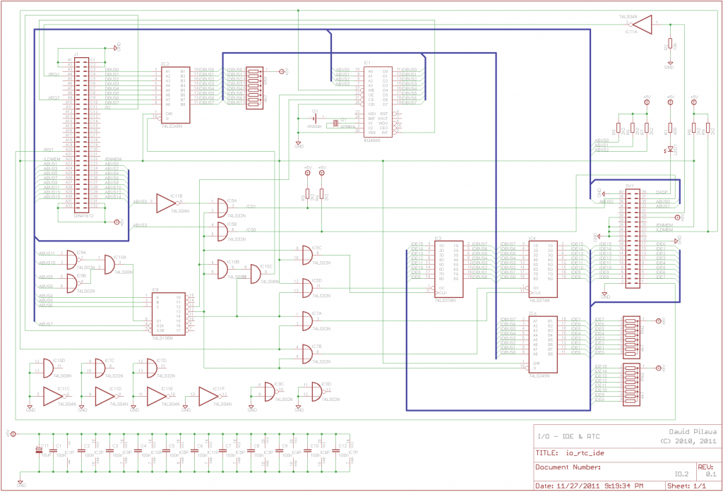
Although not tested at all, I am publishing a draft schematic for the new board here, just to share the concept. In a few days I should be sending the design to an inexpensive prototyping board house in Poland I have found recently. Altogether, the board should cost me around $40 – way cheaper than the cheapest service I have been using until now (BatchPCB). I am not sure what the quality is going to be, but this is a reasonable price for prototyping. Once the design is tested, I will update the consolidated schematics sheets, too.
That’s all for now. I will share the results of IDE tests as soon as I build the new board. Stay tuned.

What you described in this report will allows you to access the disk media in a per-sector basis (please correctly if I am wrong). My question is: how do you plan to manage several files (not just a single large “raw partition”)? What idea you have in mind for a file system?
You are absolutely right. This interface will (hopefully) allow me to read and write raw sector data from IDE devices. Implementing a file system is a different story. Honestly, I am not sure yet what I will implement. Read-only FAT seems to be a reasonable starting point. If I ever get to the point when I’ll be porting MINIX then the MINIX file system will be an obvious choice.
Impressive project!
Have you had trouble getting the BQ4845 to switch between 12 and 24 hour mode? I have it basically working but chnging the 12/24 bit in the control register does not seem to have any effect.
Regards,
David.
Hi David, I haven’t tried this. My I/O card has been gathering dust for some time, but I will definitely give it a try once I hook it up to the CPU again.