Believe it or not but I am still waiting for memory and UARTs board from BatchPCB. I am waiting for a redo after my last shipment was lost but looks like these guys assign lower priority to redo jobs. All in all, I have been waiting for two boards since November 1 last year. My design has just been panelized. It sucks.
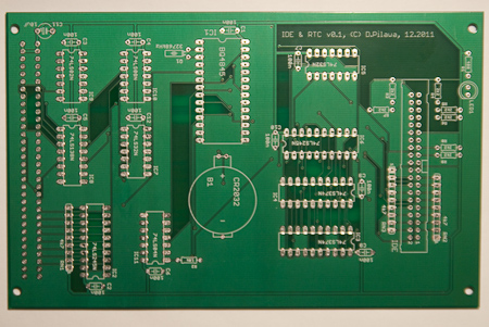
Meanwhile, I received an IDE/RTC board I ordered at a local fab house (board described here). I worried that quality would not be as good as BatchPCB’s but at a first glance I was positively surprised. Traces and ground planes revealed no pour, silkscreen was crisp, soldermask and drills were all well aligned and board edges were nice and smooth. All this cheaper and faster than at BatchPCB. This is how the bare board looked like:

The only quality-related problem I encountered when assembling this board was a pad that detached from the boards when treated it with a solder sucker during desoldering. I may have overheated the pad but this as well may indicate that these boards are not good for any kind of rework. I don’t recall this kind of trouble with BatchPCB’s boards although I am pretty sure I was desoldering components from them.
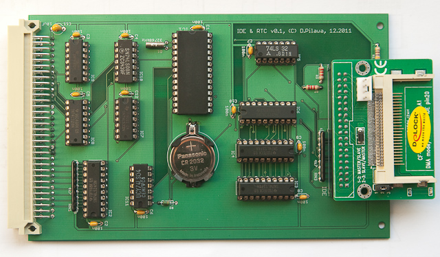
I also struggled a bit soldering the 3V battery holder but this time it was only my mistake, not the board quality issue. I was unable to find a footprint in Eagle matching the holder I had so I created my own. Unfortunately, I chose a drill size a bit too small and it took some force to push the leads through the holes. Other than that, everything went rather smoothly. Here’s the final result:

The peggy board sticking out the right side of the board is an IDE – CompactFlash adapter got from eBay for 4 euros. I haven’t tried it yet but ultimately I will be using CompactFlash rather than real IDE hard drives which are big, heavy and may easily fail considering their age (although I salvaged four old drives from two PCs I had in my basement and they all seem to still work fine). Still, CompactFlash is simply more handy for development purpose, and it can be easily swapped between my computer and a PC (connected via USB reader) to exchange files.
Bring-up of RTC
Immediately after the board assembly, my first attempts to read real-time clock ticks failed. The clock seemed dead – all its registered read $ff as if it was unconnected and despite I studied the datasheet again and verified all connections it just would not work. I replaced the chip, the 32kHz crystal, even checked the battery but none of these helped. Surprisingly, the same chip connected on the breadboard immediately produced good results (i.e. the seconds register started outputting changing values). When I connected its least significant bit to the LED, it generated one-second pulses. I was stuck.
At some point I changed the power supply from a desktop lab power supply to an old AT power supply. I only did this in order to power an IDE drive, not because I suspected problems with my power lines. Out of a sudden, the RTC started ticking. I was really baffled.
Now that I knew that the problem is related to power or ground I started playing around. I tried connecting my lab power supply here and there to the boards and observed the RTC work or fail, depending on where I connected the ground. I also observed ground noise on a scope. Ground was never perfectly flat but the noise was not really that bad. At least, It had never caused problems before.
I started googling this problem and I came across this excellent article on using crystal oscillators with Maxim’s RTCs. It was an eye opener. I have been suspecting the crystal oscillator to malfunction, but only after reading this paper I realized how ignoring simple physical characteristics of a circuit got me into trouble.
A quick look at the PCB photos above reveals that I have placed a ground plane below the crystal (the crystal is this little metal cylinder right next to the big RTC chip). Ground plane in fact runs on both sides of the board, acting like a capacitor (two conductors are separated by a dielectric). For the low-power clock crystal to work, the circuit must load the crystal with correct capacitive load. If the capacitive load is greater than the crystal’s parameter, it will slow down or fail to swing completely. I guest this is exactly what happened in my case – power planes around the crystal caused stray capacitance of the board layout which sometimes prevented the crystal from starting (depending on how/where I actually connected the wires to the boards, although this phenomenon I don’t really grasp).
From the Maxim paper I learned that the following guidelines should be followed for board layouts with extremely low power crystals:
- crystal should be as close as possible to the chip inputs (this condition was met on my board)
- trace width should be kept minimal
- no other signals should run directly below the crystal or its traces to the chip
- a guard ring may be routed around the crystal to prevent it from noise from neighbouring chips or traces
- for the same reason a local ground plane may be placed on a layer immediately below the crystal (but only in one layer to prevent stray capacitance)
The board layout I am publishing today already has all the above recommendations implemented. I have not tested yet how it improves clock crystal performance, but I am pretty sure that stray capacitance was a primary cause for failures. For now, as a dirty workaround, I have learned how to connect power so that the RTC works.
Bring-up of IDE
IDE bring-up, on the other hand, went smoothly. I was worried that I had made mistakes in IDE circuitry, but it worked at the very first try. I connected and old 13GB IBM hard disk to the controller and I was immediately able to send IDE commands to it. It responded to spin-up, spin-down and read sector commands. At the same times the HDD activity LED blinked nicely to indicate drive business. One of the first exciting things to do was reading drive identifier, which every IDE device exposes (IDE command $EC). Full list of ATA/ATAPI commands is here.
The sequence of steps to set-up IDE and read IDE identifier block (512 bytes) is the following:
- reset IDE (write to control register)
- spin-up drive (send command $E1 to command register)
- wait for RDY=1 and BUSY=0 flags (by polling status register or using interrupts)
- issue drive identify command (send $EC to command register)
- wait for DRQ=1 and BUSY=0 flags (again, by polling status register or using interrupts)
- read 256 words from 16-bit data I/O port
- interpret data just read (e.g. drive label – 40 bytes at offset $36, drive size in sectors – 4 bytes at $78)
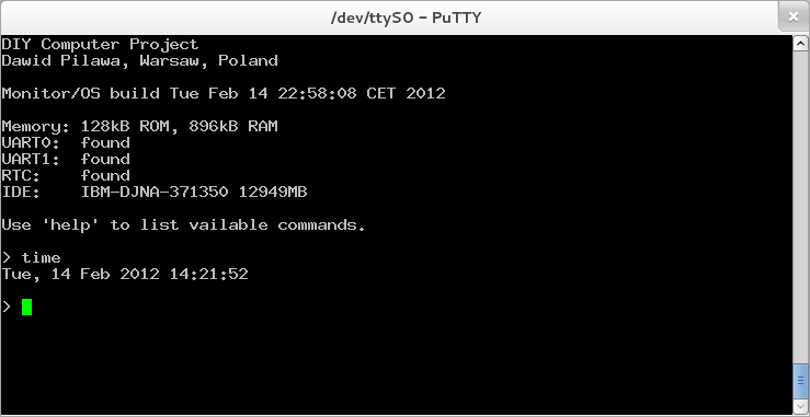
The final result of my recent experiments is below and shows that both IDE and RTC are alive. The line staring with ‘IDE:’ presents selected information retrieved from drive identifier block (in this case my old 13GB IBM hard-disk was connected). The ‘time’ shell command simply displays current time read directly from RTC registers.

It is now time to think of implementing a filesystem, like read-only FAT16 or something custom, simpler but with write support. I am thinking of leaving only a simple bootloader program in ROM and booting a Monitor/OS from IDE device completely. This would allow me to give up using the EPROM emulator which, although extremely helpful, is not very handy and increases setup/cleanup time when I need to free up my desk for other activities.
What next?
As usual, I have uploaded the updated schematics and board layouts here. I think I am getting close to declaring basic hardware completed. It is high time to make this project more software-oriented and move on to things I have been declaring since long time ago, like C compiler, linker and real multitasking OS.