It’s been a long time since I last posted on this site or did anything related to the project. Way too long. My paying job has had me extremely busy lately. Add to this a long awaited apartment flip we had, sooner than expected due to our contractor’s change of schedules and you’ve got the story. I really hope things will go faster now. Otherwise this project will take years to even get off ground.
An obvious follow-up on microcode sequencing post from more that two months ago is adding faults and interrupts mechanism to the design. Faults and interrupts are similar, there is only one particular difference. Interrupts occur asynchronously but are handled on instruction boundaries only, whereas faults may break the processing flow within the instruction’s execution cycle. Here is the idea how to do it.

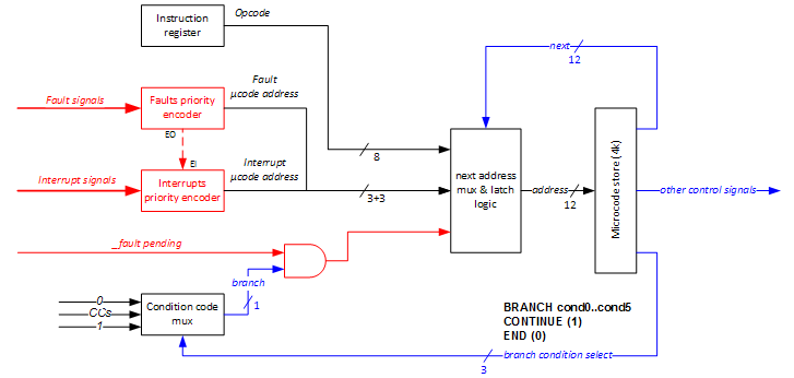
Red elements are extensions to previous design. The idea is to use two priority encoders based on 74LS148 chips (8-to-3 line) and use their outputs as alternative feeds to next address multiplexer. The 74LS148 encodes three lines to 3-bit binary ensuring that only the highest order data line is encoded. By cascading wiring, faults encoder has higher priority than interrupts encoder. The address of the fetch microcode instruction, previously indicated as a hardwired input to the next address mux, is now considered as the combined address encoded when no data input is asserted to any of the encoders. In other words, we fetch only when there are no faults and no interrupts pending. Another modification is the removal of fetch control signal – I realized it was not necessary as it may be easily replaced by sacrificing a dedicated next address, say $fff (12-bit, all 1) and adding some simple additional circuitry (OR gates in this case).
With the above design, we have three inputs to the next address mux:
- absolute ‘next’ field from the microcode store
- output from the priority encoders (fault 0..7 microinstruction address, or interrupt 0..6 microinstruction address, or fetch microinstruction address)
- contents of the instruction register
Which of these is fed as and address of the next microinstruction to execute depends on:
- the ‘next’ address (or more specifically, whether it is $fff or not)
- the branch signal from the condition code mux
Now, next address mux will assure that:
- IR (opcode) is chosen as a direct address to the microcode store if and only if ‘next’ is $fff and branch signal is 1 (this only happens at the end of fetch microinstruction)
- ‘next’ address is chosen if and only if branch signal is 1 (CONTINUE or selected condition met) and ‘next’ is not $fff
- priority encoders output is chosen if and only if branch signal is 0 (END or selected condition is not met)
Now, whenever any of the interrupt lines is asserted (but there is no fault pending), the interrupt should be serviced on instruction boundaries, i.e. whenever branch signal is zero. This happens whenever the selected branch condition is not met (and instruction execution ends) or when END condition is used, consequently setting branch signal to hardwired zero. This behavior (using END condition) was previously referred to as unconditional fetch. Now, with priority encoders and fetch being a lowest priority output, it is rather unconditional fault-interrupt-fetch (in exactly this order). No matter how it is called, it works fine for interrupts. The priority encoder will deliver the microcode address of a proper interrupt pseudo-instruction, that will consequently jump via interrupt vector to the interrupt service routine code somewhere in the memory. Of course, the microcode will also suppress any further interrupts by setting a dedicated flag in a yet-to-be-designed machine status register (MSR). This flag will be deasserted on the next RET instruction, right before the control is returned to where we have left it.
For faults, we need a way to enforce END (reset branch signal) whenever a pending fault appears. This may be easily achieved by ANDing the branch signal with low active fault pending signal indicating the presence of an unserved fault and clocking next address latch (by using one of the offset clocks). This way, instruction execution breaks even before the nearest microinstruction boundary, and the priority encoder outputs an address of a proper fault microinstruction. Of course, fault handling code needs to do any cleanup that may be required in such case.
One last thing that should be noted here is clocking. The clock signal used for latching the next address mux and latch logic block should be offset to the master clock used in the datapath. Otherwise signals will not have enough time to settle before the next microcode address is determined, which may result in dispatching incorrect control signals to the system. I plan to have two system clocks overlapping by 90 degrees, say CLK0 and CLK1. Looks like the next address latch is the first good reason to justify the existence of CLK1. In this approach, on CLKo (master clock) going high, we will latch the register contents (including the IR) and condition codes. The system will settle before the positive edge of CLK1 arrives, and the next microcode instruction address will be determined correctly. Then also enough time remains until next CLK0 pulse for the control signals to do their job.